Application Note: Ultimate Solution for Ultra-Thin-Film Systems
Enabling Accurate Elastic Modulus Measurements of 10 nm Thin-Film Systems with Nanoindentation Tests
Reliable measurements of the elastic modulus of thin films is particularly challenging due to the so-called substrate effect. The prevalent rule of limiting indentation depth to 10% of the coating thickness to avoid the substrate influence in the mechanical properties is challenging to ensure, especially when the film thickness goes below 200 nm. The tip radius can be one of the many factors limiting the application of the Oliver-Pharr Model1 on elastic modulus calculation, as well as the surface roughness. With the newly developed ultra-low-noise xProbe™ transducer combined with the Intrinsic Thin Film Property Solution (iTF)2, quantitative mechanical properties from nanoindentation tests on 10 nm thin-film systems becomes possible.
Contents include:
KEYWORDS: Nanomechanical Test Instrument; Hysitron; Bruker; Application Note; AN1514; Nanoindentation; TI 950; TriboIndenter; xProbe; iTF; Thin Films

Procedure
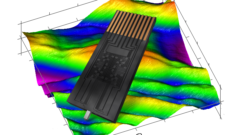
The experiment was conducted using Bruker's Hysitron® TI 950 TriboIndenter® equipped with an xProbe and cube-corner probe in quasi-static mode. The xProbe is a MEMS-based transducer with a noise floor similar to that of a contact mode atomic force microscope (AFM). The linear actuation allows for direct and fully quantitative measurements without the need of modeling, which leads to more precise mechanical properties estimation and higher analysis throughput. Nanoindentation tests (Figure 1)
were performed on the ultra-thin-film sample using load control feedback mode.

Results
Unloading segments of each indentation were analyzed using the Oliver-Pharr Model1, where the stiffness is calculated from the unload segment. Based on that, as well as probe calibration, the elastic modulus of nanoindentation can be directly calculated with non-linear substrate effect to the thin film based on the equation:

where S is the unloading stiffness and A is the projected contact area. Reduced elastic modulus and hardness are plotted in a function of contact depth (Figure 2). The initial increase in the mechanical properties can be related to the surface roughness and the interfacial surface layer on the surface.
Applying iTF analysis to the stiffness, depth, and load profile, the intrinsic elastic modulus of the film will be calculated almost instantaneously. iTF analysis utilizes the known area function, the contact geometry, and the load and stiffness as an input for the three equations between the elastic deflection and the contact radius.
Unlike finite element analysis, the model does not need any presumed modulus for the thin film. By numerically solving these equations, the film modulus (Figure 2) and plasticity parameter are calculated.

Conclusions
By combining the ultra-low-noise xProbe transducer and analytical Intrinsic Thin Film Solution, we quantitatively determine elastic properties of the ultra-thin-film systems of 10 nm or below.
References
- Li, H. and J.J Vlassak, Determining the elastic modulus and hardness of an ultra-thin film on a substrate using nanoindentation. Journal of Materials Research, 24, 1114–26, 2009.
- Oliver, W.C. and G.M Pharr, An improved technique for determining hardness and elastic modulus using load and displacement sensing indentation experiments. Journal of Materials Research, 7, 1564–83, 1992.
Authors
- Anqi Qiu, Ph.D. (anqi.qiu@bruker.com)
Hysitron, TriboIndenter, and xProbe are trademarks of Bruker Corporation. All other trademarks are the property of their respective companies. © 2018 Bruker Corporation. All rights reserved. AN1514, Rev. A0